
|
It is currently Fri May 17, 2024 5:52 am |
|
All times are UTC - 5 hours [ DST ] |

|
Page 1 of 2 |
[ 23 posts ] | Go to page 1, 2 Next |
| Print view | Previous topic | Next topic |
Rotor head comparison questions
| Author | Message | ||
|---|---|---|---|
 |
So, this does not include the original Rotorway Scoripion head with cable collective.
My question i is the AW95/Hobbycopter/Skytwister main rotor head just a knock off of the rotorway scorpion rotor head? For a true part 103 ultralight helicopter would the AW95 rotor head safe for actually flying around? I have seen plenty of videos of guys hovering around, but none going thru Translational lift and climbing out to pattern altitude, or flying locally at altitude. I want something that is easy for the average builder with common shop tools for most of the build and will not break the bank Thanks David |
||
| Mon Jan 23, 2023 7:09 pm |
|
||
 Joined: Thu Nov 07, 2013 12:56 am Posts: 2994 Location: VERY LOW LOW LOW EARTH ORBIT Has thanked: 2856 times Been thanked: 3680 times |
form fits function
Scale down a Rotorway head or an AW head they both do the same job Seen a Chadwick helicopter 4 bladed head that had a strap pack like a Hughes 500 16 ft rotor span an ultra lite Seen a strap pack like a bell Jet Ranger on two styles of ultra lite helicopters AW 95 with Doug Swickerd had a Solar turbine . Most ultra lite helicopters are flown by hobbyists and don't fly like a heavier machine at higher altitudes . Here's an old site with big sources http://aviastar.org/index.html |
||
| Mon Jan 23, 2023 7:43 pm |
|
||
|
|
Hillberg wrote: form fits function Scale down a Rotorway head or an AW head they both do the same job Seen a Chadwick helicopter 4 bladed head that had a strap pack like a Hughes 500 16 ft rotor span an ultra lite Seen a strap pack like a bell Jet Ranger on two styles of ultra lite helicopters AW 95 with Doug Swickerd had a Solar turbine . Most ultra lite helicopters are flown by hobbyists and don't fly like a heavier machine at higher altitudes . Here's an old site with big sources http://aviastar.org/index.html Chadwick I did not know about The strap pack was the Ultrasport 254, right. Used piano wire to make the strap packs, also like used in a UH-1 Well my concern is the bearings setup. I have no problem flying higher as long as I know that the head is ok for constant flight and not just for hovering. Full Autos are fun |
||
| Mon Jan 23, 2023 8:33 pm |
|
||
|
Joined: Thu Nov 07, 2013 12:56 am Posts: 2994 Location: VERY LOW LOW LOW EARTH ORBIT Has thanked: 2856 times Been thanked: 3680 times |
The MD 500 not only a strap set up but had a spherical bearing riding on a pin to keep the flapping & feathering at the same point. Both the Huey and 206 had strap packs with needle bearings riding on the yokes
early scorpions had double ball bearings for flapping and feathering on a trunnion [teeter/rocking] with collective cable linked to both grips - A Teleflex cable to swash plate and a collective system with head of an exec scaled down is good You do not have the required permissions to view the files attached to this post. |
||
| Mon Jan 23, 2023 9:00 pm |
|
||
|
|
Hillberg wrote: The MD 500 not only a strap set up but had a spherical bearing riding on a pin to keep the flapping & feathering at the same point. Both the Huey and 206 had strap packs with needle bearings riding on the yokes early scorpions had double ball bearings for flapping and feathering on a trunnion [teeter/rocking] with collective cable linked to both grips - A Teleflex cable to swash plate and a collective system with head of an exec scaled down is good Scaled down how far ? 15-20%? |
||
| Tue Jan 24, 2023 8:53 pm |
|
||
|
Joined: Thu Nov 07, 2013 12:56 am Posts: 2994 Location: VERY LOW LOW LOW EARTH ORBIT Has thanked: 2856 times Been thanked: 3680 times |
Scale according to design loads smaller by 20 percent will that afford the safety margin ?
keeping the loads scaled too? Less gross weight less horse power material load will dictate size. [Aircraft Spruce Catalog has nice material strength charts] As with any project what materials, what mission. what monies. |
||
| Tue Jan 24, 2023 10:12 pm |
|
||
|
|
Hillberg wrote: Scale according to design loads smaller by 20 percent will that afford the safety margin ? keeping the loads scaled too? Less gross weight less horse power material load will dictate size. [Aircraft Spruce Catalog has nice material strength charts] As with any project what materials, what mission. what monies. Yep, done the math on the grip loads, blade loads, size for lift based on 550lbs gross weight, then added 1.5 as a safety margin. pretty much done with all the math. Now looking at bearings, may go with AC bearings, but afraid of ratcheting during flight, will have to make a test rig to apply artificial centripetal loads and see it they still will rotate smoothly. If not then ball with needle thrust bearings. I want a real part 103 helicopter, that I can do 50 mile cross countries in. Lots to do. Thanks for the help Don David |
||
| Wed Jan 25, 2023 9:20 am |
|
||
|
Joined: Thu Nov 07, 2013 12:56 am Posts: 2994 Location: VERY LOW LOW LOW EARTH ORBIT Has thanked: 2856 times Been thanked: 3680 times |
A standard of X3 on most areas will do
X7 for critical single point failure points like TT straps , Latch bolts and pins, Rescue hoist cables... Looking good  If you can give it an easy daily inspection before flight the 1.5 will do too.  |
||
| Wed Jan 25, 2023 2:06 pm |
|
||
|
|
Hillberg wrote: A standard of X3 on most areas will do X7 for critical single point failure points like TT straps , Latch bolts and pins, Rescue hoist cables... Looking good If you can give it an easy daily inspection before flight the 1.5 will do too. Thanks, will use those standard. you are the only one I know who has designed his own and flown it. Thanks Don David |
||
| Wed Jan 25, 2023 3:48 pm |
|
||
|
Joined: Thu Nov 07, 2013 12:56 am Posts: 2994 Location: VERY LOW LOW LOW EARTH ORBIT Has thanked: 2856 times Been thanked: 3680 times |
Anytime
I've flown other helicopters that others built and remedied minor control issues The Mini 500? Had a guy who said I could take it up anytime , Small voice in my head said 'Hell NO' I knew its flaws in design As tne machine is used and abused the limits come into play as cyclic loads and ware/flaws introduced eat away on the materials used. A new machine has 100% margin after a few years the margin shrinks - So you "over build" to compensate |
||
| Wed Jan 25, 2023 4:32 pm |
|
||
|
|
The feathering bearings I was considering a AC bearing instead of needle bearings and coupled with a thrust bearing
Your take? |
||
| Wed Jan 25, 2023 8:58 pm |
|
||
|
Joined: Thu Nov 07, 2013 12:56 am Posts: 2994 Location: VERY LOW LOW LOW EARTH ORBIT Has thanked: 2856 times Been thanked: 3680 times |
Thrust loaded ball is okay even a mix of what's needed for span wise loads, chord wise loads and lifting loads.
Hughes 300s, Sikorskys, and Robinson use a bearing stack up of multiple bearings - Tension and feathering uses A Rotorway had two bearings for collective thrust loads [tension feathering for collective only]and a set of gimble bearings for cyclic feathering and flapping (lower cyclic loads adding to bearing life) [AKA Bell 47] A heavily loaded bearing will cycle out and bind in the races ratcheting with higher break away loads that feed back to the control stick. Heavier loads = higher costs Enstrom Helicycle and the Rotorway went to an elastimeric thrust bearing Bell 47 had a massive bearing for thrust loads - You could use a propeller thrust bearing or a scaled down bearing ie: Big Balls and races...More contact surface area |
||
| Wed Jan 25, 2023 11:49 pm |
|
||
|
|
Hillberg wrote: Thrust loaded ball is okay even a mix of what's needed for span wise loads, chord wise loads and lifting loads. Hughes 300s, Sikorskys, and Robinson use a bearing stack up of multiple bearings - Tension and feathering uses A Rotorway had two bearings for collective thrust loads [tension feathering for collective only]and a set of gimble bearings for cyclic feathering and flapping (lower cyclic loads adding to bearing life) [AKA Bell 47] A heavily loaded bearing will cycle out and bind in the races ratcheting with higher break away loads that feed back to the control stick. Heavier loads = higher costs Enstrom Helicycle and the Rotorway went to an elastimeric thrust bearing Bell 47 had a massive bearing for thrust loads - You could use a propeller thrust bearing or a scaled down bearing ie: Big Balls and races...More contact surface area Thanks Don David |
||
| Thu Jan 26, 2023 8:44 am |
|
||
|
Joined: Tue Mar 24, 2020 5:39 am Posts: 1056 Location: France Has thanked: 649 times Been thanked: 1733 times |
HI,
I am really interested in trying to understand all of this ... but I can't find the good translations in french of gimbal bearings , thrust bearings and feathering bearings what are gimbal/ feathering and thrust bearings and where are they on the rotorway rotor head please ? in my understanding on the rotor way there are 2 bearings at each side of the oval donut one bearing in the cubes which are located in the Donut and that prevent the blades to resist the centrifugal force (so that the can't get extracted) and one in the square metal part located at each end of the oval Donut the blades have axles at their root and those axles (axis?) are going through both the 2 bearings , the bearing which is outside of the oval donut is also in an aluminium cage fitted with a screw which is certainly there to make an adjustment (of what I don't know) please help me out of my ignorance I had worked on using the rotorway system to make a personal version of the michel cross regulator .. i had found this toro head really simple I had even found those famous elastomeric bearings .. but I have delayed all of this but it is still in my mind |
||
| Fri Jan 27, 2023 3:08 am |
|
||
|
Site Admin  Joined: Tue Sep 02, 2014 7:45 am Posts: 10083 Location: Poona, Qld, OZZY Has thanked: 21635 times Been thanked: 6118 times |
Thrust bearings are bearings used to stop a shaft from pushing into something... such as a crank shaft with a propeller on it, the propeller would try to drive the crank forward (or pull it out ) of the motor. The center bearing usually had thrust bearing surfaces to stop the crank being able to move forward or backwards
gimbal bearings are the bearings in a rotor head that allow the head to tilt from side to side and forward and backwards... the gimbal bearings don't rotate, they just support and allow smooth movement Hopefully some of the heli boys can explain them on the actual Rotorway head      _________________ I do all of my own stunts..... most of them are even planned! Ok, Ok.... some of them are planned.. If electricity comes from ELECTRONS, then surely morality comes from MORONS?? |
||
| Fri Jan 27, 2023 3:17 am |
|
||
|
Joined: Tue Mar 24, 2020 5:39 am Posts: 1056 Location: France Has thanked: 649 times Been thanked: 1733 times |
thank you murray, what I would need is to locate all of those bearing on the rotorway rotorhead
with your answer I understand that the thrust bearings are in the 2 cubes located inside the oval donut ? I am right I must be the elastomeric braring right ? what about the gimbal bearings and the feathering bearing, it is the same name for the same bearing locate at the end of the oval donut of the rotorway head ? |
||
| Fri Jan 27, 2023 3:24 am |
|
||
|
|
Girodreamer wrote: thank you murray, what I would need is to locate all of those bearing on the rotorway rotorhead with your answer I understand that the thrust bearings are in the 2 cubes located inside the oval donut ? I am right I must be the elastomeric braring right ? what about the gimbal bearings and the feathering bearing, it is the same name for the same bearing locate at the end of the oval donut of the rotorway head ? This is the AW95 head, very close to the Rotorway head, it will do to explain bearing placement. Item "C" Is the feathering bearing, it allows rotation on the blades pitch axis Item "B" is the feathering bearing block, there are two of these in opposite ends of the blade grip. Not used in this head is the thrust bearing, it takes the centripetal loads of the blades. It is outboard the feathering bearing, between the feathering bearing and the rotor hub. Only on the inboard feathering bearing. The gimbal bearing is in the center support "I", the pivot blocks have the gimbal bearings to allow the head to teeter to allow the rotor system to take the flapping loads needed absorb the lead lag loads. Hope this helps. David 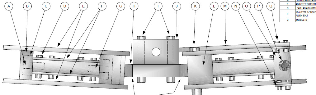 Last edited by skyguynca on Fri Jan 27, 2023 1:22 pm, edited 2 times in total. |
||
| Fri Jan 27, 2023 12:54 pm |
|
||
|
|
Girodreamer wrote: thank you murray, what I would need is to locate all of those bearing on the rotorway rotorhead with your answer I understand that the thrust bearings are in the 2 cubes located inside the oval donut ? I am right I must be the elastomeric braring right ? what about the gimbal bearings and the feathering bearing, it is the same name for the same bearing locate at the end of the oval donut of the rotorway head ? Ok, here is the Rotorway Scorpion Head. Ok the Gimbal Bearing is Item "6", this is the teetering axis for the head to teeter up and down. Item "13" is the feathering block Item "14" is the feathering bearing, this is what the blade pitch axis rotates on Item "15" is the thrust bearing, this takes the centripetal loads to prevent the feathering bearing from failing in axial loads. It is outboard the feathering bearing, between the feathering bearing and the rotor hub. Only on the inboard feathering bearing. Item "16" is the thrust washer the bearing rides on. Like the AW head there are two fethering blocks per blade grip. Hope this helps David 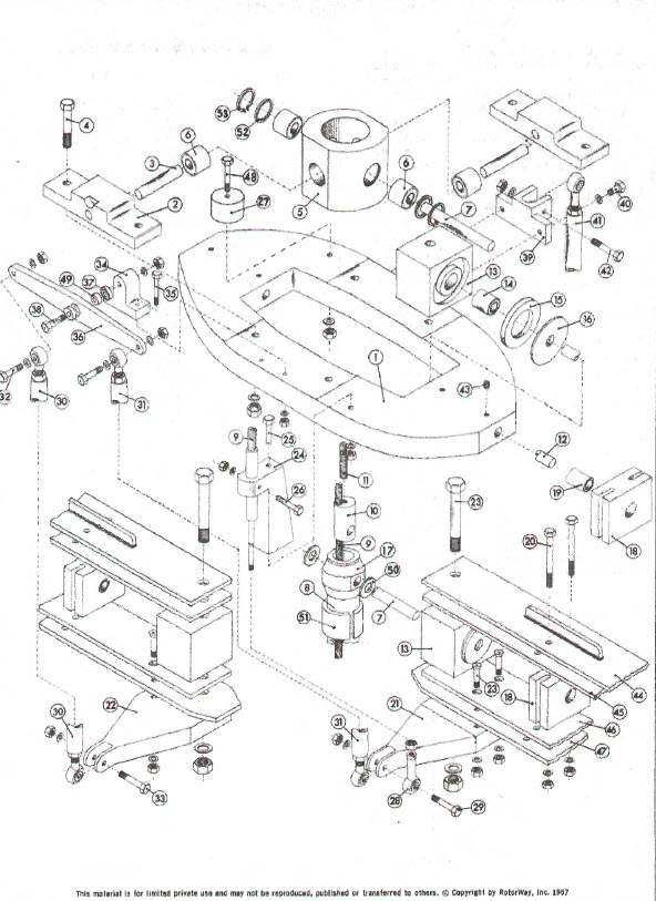 |
||
| Fri Jan 27, 2023 1:13 pm |
|
||
|
|
Girodreamer wrote: thank you murray, what I would need is to locate all of those bearing on the rotorway rotorhead with your answer I understand that the thrust bearings are in the 2 cubes located inside the oval donut ? I am right I must be the elastomeric braring right ? what about the gimbal bearings and the feathering bearing, it is the same name for the same bearing locate at the end of the oval donut of the rotorway head ? As Don and I were discussing, when using needle bearings for the feathering axis (pitch) a thrust bearing is used to absorb the centripetal loads to prevent racheting in the needle bearings. The 5200 bearing you mentioned is a AC Bearing, Angular Contact bearing. Bigger harder balls and a bigger harder race to absorb loads not only radially but also axially, hence a combined load on a angle. There are used in alot of stacked bearing heads. The load is shared by the "Matched" bearings so each individual bearing load is so small compared to the max load of each individual bearing in the stack you get a really long life from the bearing. Now this is another type of head that uses a tension and torsional strap, known as a "TT strap" If you want to know about it, let me know and I will post a parts breakdown and explain it to you also. It was used in the Bell Jet Ranger (OH-58) and the Bell Iroquois (UH-1 ). Very simple head, fewer parts. David |
||
| Fri Jan 27, 2023 1:39 pm |
|
||
|
Joined: Tue Mar 24, 2020 5:39 am Posts: 1056 Location: France Has thanked: 649 times Been thanked: 1733 times |
Hi David,
thank you very mutch for all those explainations ... now I understand what don was explaining ... the language barrier often prevents me from understanding all what you say in technical English I fing it crazy that those rotor heads have so tiny "jesus bolts" ... for example the bolt n°23 is alone and seems to play a major rôle in holding the blades ... in gyro we are used to put plenty of useless bolts at the root of the blades .... here I see one tiny screw .... if I was to make such a head I would use a an X-rayed screw.... analyse your drawing I love this rotor head ... for the moment I will focus on this system trying to understand it before you put an other part break down |
||
| Fri Jan 27, 2023 4:57 pm |
|
||
|
|
Page 1 of 2 |
[ 23 posts ] | Go to page 1, 2 Next |
|
All times are UTC - 5 hours [ DST ] |
Who is online |
Users browsing this forum: No registered users and 37 guests |
| You cannot post new topics in this forum You cannot reply to topics in this forum You cannot edit your posts in this forum You cannot delete your posts in this forum You cannot post attachments in this forum |